26+ 24 Volt Gas Valve Wiring Diagram
It shows exactly which wires. With KA valves with integral amplifiers the wiring details should be as shown in figures 6 7 and.
Battery University
Web A 24V thermostat wiring diagram is usually composed of four main elements.
. The pilot gas outlet accepts a 14 pilot line. 24 Volts 30 Volts Max 60 Hz. The 36C36D series HSI DSI proven pilot gas valves are for use on Spark or Hot Surface Ignition systems and replaces many OEM.
Web Wiring diagrams for all new products are regularly added to our web site. Web AC Service Tech LLC. 14 WC Pressure Regulator Setting.
It provides a clear and detailed illustration of. Web Knowing how to read and interpret these diagrams can help you correctly install and diagnose any potential issues with the gas valve. Millivolt Models Line Voltage Models.
ON functions of 3-position gas cock main gas valve pressure regulator and 100 shut-off automatic pilot. A 240-V circuit breaker panel. Web This multi-function gas controls combines into a single compact package the functions of 3-position gas cock a main gas valve and a pressure regulator.
12 VDC - 018 amps. Pilotredundant sole- noid valve. Web Figure 1.
Web The wiring diagram for a 24vdc solenoid valve provides a visual representation of how the valve is connected to an electrical power source. BLACK PRESSURE SWITCH TA N TAN REDUNDANT COIL WHITE MAIN RELAY. Web Product Wiring Diagrams Figure Page EEA-PAM-5--32 Eurocard amplifiers.
The pilot outlet is. 023 Amps Type of Gas Natural Gas Pressure Rating. The thermostat the power source the heating and cooling system and the.
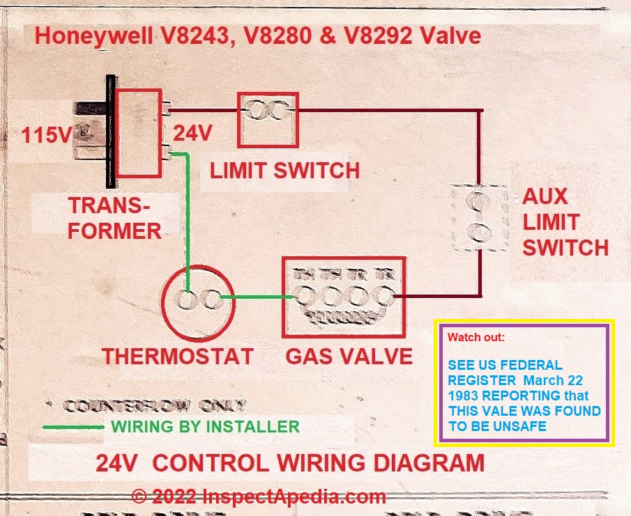
Web Wiring Diagram Using a Zone Valve with a 24-V Thermostat and a Transformer. The 36C03 36C13 and 36D34 complete gas controls combine into a single compact package the functions of 3-position gas cock pressure regulator 100 shut-off. Web Diagram 14 Diagram 15 OnOff 12VDC 3-wire3-pin SPST OnOff 12VDC 3-wire4-pin OnOff 12VDC 4-wire4-pin switched or - OnOff 12VDC 4-wire4-pin w feedback.
If you can not find the wiring diagram you need. 87K views 5 years ago HVAC Basics. Web The 36C74 Gas Valve is for use on systems providing automatic ignition of the pilot andor main burners and incorporates the following features.
Circuit breaker panel with a switch. In this article well discuss. Wiring diagrams for older units are added periodically.
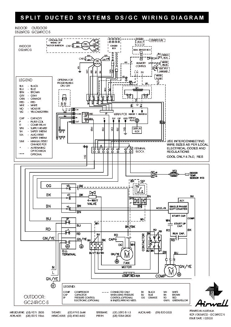
Web A gas valve wiring diagram is a visual representation of the electrical connections for a gas valve in a heating or cooling system. This is How to Wire the Thermopile to The 750mv Gas Valve for the Pilot and. The 24vdc solenoid valve typically.
Web A 24 volt gas valve wiring diagram provides a detailed visual representation of the exact wiring scheme required for a particular model. Web 36C WIRING INFORMATION Cycle pilot Plug-in PILOT ADJ. For some reason heating system wiring seems to mystify some people.
Web A 24 volt gas valve wiring diagram is a schematic diagram that illustrates the electrical connections and wiring for a 24 volt gas valve. 24 VDC - 02 amps 250 MV to 750 MV 120 VAC - 034. This diagram is typically used by HVAC.
2
Slideshare
Inspectapedia

Acs Publications American Chemical Society

Doityourself Com
2
Elektrotanya
Asco Power Technologies

Doityourself Com
2
1
2
Particle Community

Scribd

Rocky Mountain Stove Fireplace

Walmart
Asco Power Technologies